In this article, we will delve into the concepts of Maximum Transmission Unit (MTU) and Maximum Segment Size (MSS). Although they are closely related, these two networking parameters have different purposes and implications for network performance. By understanding the function and impact of each, we can better optimize network settings for efficiency and reliability.
Glossary
- MTU: Maximum Transmission Unit
- MSS: Maximum Segment Size
- MAC: Media Access Control
- IP: Internet Protocol
- TCP: Transmission Control Protocol
- FCS: Frame Check Sequence
Understanding the Network Encapsulation Process
One way to visualize the encapsulation process is to imagine it as a series of layers, each adding its own header and/or footer to the data payload. Here is a detailed breakdown of how the encapsulation process works:
Here’s a simplified explanation:
- Application Layer: This is where the data starts. It can be any data generated by applications such as a web page or email.
- Transport Layer: The data from the application layer is passed to the transport layer. This layer adds a header to the data which includes information such as the source port and destination port. If TCP is used, the header is typically 20 bytes, while for UDP it’s 8 bytes.
- Network Layer: The data (now called a segment) is passed to the network layer. Here, an additional header is added which includes the source IP and destination IP addresses. The header for IPv4 is 20 bytes.
- Data Link Layer: The segment (now a packet) is further encapsulated at the data link layer. An additional header is added which includes the source MAC and destination MAC addresses, the EtherType, and a Frame Check Sequence (FCS). The header for Ethernet is typically 18 bytes.
- Physical Layer: Finally, the packet (now a frame) is converted into bits and sent to the destination over the physical medium (like Ethernet cable or Wi-Fi).
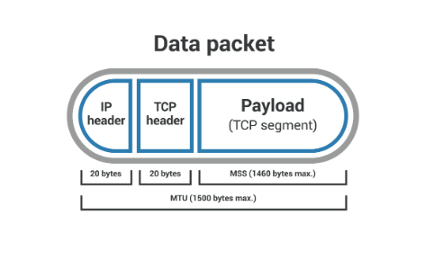
This process of adding headers at each layer is called encapsulation. It helps ensure that the data is delivered correctly from the source to the destination. Note that the size of the data decreases at each layer due to the addition of these headers. For instance, in Ethernet, the Maximum Transmission Unit (MTU) is typically 1500 bytes, but after accounting for headers, the Maximum Segment Size (MSS) is usually 1460 bytes.
The selected text is a visual illustration of how data is encapsulated and transmitted across different layers of a network. The process starts from the Application Layer (Top Layer) and goes down to the Physical Layer (Bottom Layer).
Application Layer Data
        ↓
+-------------------+ <--- Application Layer
|   Application     |
|     (Data)        |
+-------------------+
        ↓
+-------------------+-------------------+-------------------+-------------------+-------------------+
|   Transport Layer |   Headers (20 bytes for TCP, 8 bytes for UDP)             |
|   Headers         | Source Port (2 bytes)  | Destination Port (2 bytes)       |
|   +---------------+-------------------+-------------------+-------------------+
|   | Source Port   | Destination Port  | Sequence Number (4 bytes) | Acknowledgment (4 bytes) |
|   +---------------+-------------------+-------------------+-------------------+
        ↓
+-------------------+-------------------+-------------------+-------------------+-------------------+
|   Network Layer   |   Headers (20 bytes for IPv4)                          |
|   Headers         | Source IP (4 bytes)  | Destination IP (4 bytes)         |
|   +---------------+-------------------+-------------------+-------------------+-------------------+
|   | Source IP     | Destination IP    | Time to Live (TTL) (1 byte)         |
|   +---------------+-------------------+-------------------+-------------------+
|   | Header Length (1 byte) | Type of Service (1 byte)                       |
|   +---------------+-------------------+-------------------+-------------------+
        ↓
+-------------------+-------------------+-------------------+-------------------+-------------------+
|   Data Link Layer |   Headers (18 bytes for Ethernet)                      |
|   Headers         | Source MAC (6 bytes)  | Destination MAC (6 bytes)       |
|   +---------------+-------------------+-------------------+-------------------+-------------------+
|   | Source MAC    | Destination MAC   | EtherType (2 bytes)  | Frame Check Seq. (4 bytes)  |
|   +---------------+-------------------+-------------------+-------------------+
        ↓
+-------------------+
|   Physical Layer  | ---> Sent to the destination
|     (Bits)        |
+-------------------+
So, after clearly explaining encapsulation, let’s start with the frame. The frame is the chunk of Data (Payload) we sent to Layer 2-(Ethernet). Ethernet, by default, has a maximum size of 1518 bytes.
+--------------------------+
|      Payload             |
|   (46-1500 bytes)        |
+--------------------------+
That includes a 14-byte header consisting of the Source and Destination MAC address and a type field and a footer that includes the CRC (cyclical redundancy check), which checks to see if their data was corrupted or modified in transit.
+----------------+-------------------+-------------------+-------------+------------------+----------+
|   Preamble     | Destination MAC   |    Source MAC     | EtherType   |     Payload      |   FCS    |
|   (8 bytes)    |    (6 bytes)      |     (6 bytes)     |  (2 bytes)  | (46-1500 bytes)  |(4 bytes) |
+----------------+-------------------+-------------------+-------------+------------------+----------+
Adding up all the bytes from the Ethernet frame, we get:
👉 8 bytes (Preamble) + 6 bytes (Destination MAC) + 6 bytes (Source MAC) + 2 bytes (EtherType) + 1500 bytes (Payload) + 4 bytes (FCS) = 1526 bytes in total.
The preamble isn’t technically part of the Ethernet frame, as it doesn’t contain any frame-related information. Instead, it helps with Ethernet communication at a physical level. It’s made up of a repeating pattern of bits that allows the receiving stations to sync their clocks with the incoming data, getting them ready for the actual data that comes next.
+----------------+-------------------+-------------------+-------------+------------------+----------+
|   Preamble     | Destination MAC   |    Source MAC     | EtherType   |     Payload      |   FCS    |
|   (8 bytes)    |    (6 bytes)      |     (6 bytes)     |  (2 bytes)  | (46-1500 bytes)  |(4 bytes) |
+----------------+-------------------+-------------------+-------------+------------------+----------+
So, if we take out the Preamble, we are left with 1518 bytes; we subtract our 18-byte header, we are left with a payload(data) of 1500 bytes that our frame can carry, and that is the maximum transmission unit (MTU)
👉 1518Bytes — 18Bytes = 1500-Bytes (MTU)
IP (Packet) header
An IP packet is the chunk of data that we send at Layer 3. If we look at the packet, it is going to have an IP header and the payload(data) that we are sending with it. The IP header is 20 bytes long. So now, if we take the 1500 bytes that our frame can carry, our MTU, we subtract 20 bytes from the header of the packet, which leaves us with 1480 bytes that our packet carries as Data.
👉 1500(MTU)Bytes — 20Bytes = 1480 Bytes
IP Header consists of multiple fields, including Version, Header Length, Type of Service, Total Length, Identification, Flags, Fragment Offset, Time to Live (TTL), Protocol, Header Checksum, Source IP Address, Destination IP Address, and Options (if any).
The total length of the IP header is typically 20 bytes.
+-------------------+-------------------+-------------------+-------------------+-------------------+
|   IP Header       |   Version (4 bits) | Header Length (4 bits) | Type of Service (8 bits) |
|   +---------------+-------------------+-------------------+-------------------+
|   | Total Length (16 bits) | Identification (16 bits) | Flags (3 bits) |
|   +---------------+-------------------+-------------------+-------------------+
|   | Fragment Offset (13 bits) | Time to Live (TTL) (8 bits) | Protocol (8 bits) |
|   +---------------+-------------------+-------------------+-------------------+
|   | Header Checksum (16 bits) | Source IP Address (32 bits) |
|   +---------------+-------------------+-------------------+-------------------+
|   | Destination IP Address (32 bits) | Options (if any) |
|   +---------------+-------------------+-------------------+-------------------+
TCP (Segment) Header
Layer 4 — is where TCP operates, so we now have a TCP header and our payload (data). The header in TCP can range between 20 to 40 bytes depending upon what options are set. if there are no options set, which is for most messages carrying data, it’s going to be a 20-byte header.
but if we take the minimum header size of 20 bytes and subtract it from the 1480 our packet can carry, we are left with an MSS of 1460 Bytes
👉 1480 Bytes — 20 Bytes = 1460 Bytes MSS
So, if we use Ethernet, we should expect to see an MSS of 1460 Bytes. If it’s not 1460, it’s okay; there may be other protocols that we accommodate for that.
Just know that, in general, our MSS is going to be 1460 when we're using Ethernet. This means that our TCP segment can carry up to 1460 bytes of data in every single message.
- Maximum Transmission Unit (MTU): The largest size of a packet or frame that can be sent in a network. For Ethernet, this is typically 1500 bytes.
- Maximum Segment Size (MSS): The largest segment of TCP data that a device is willing to receive. It is determined by subtracting the IP and TCP headers from the MTU.
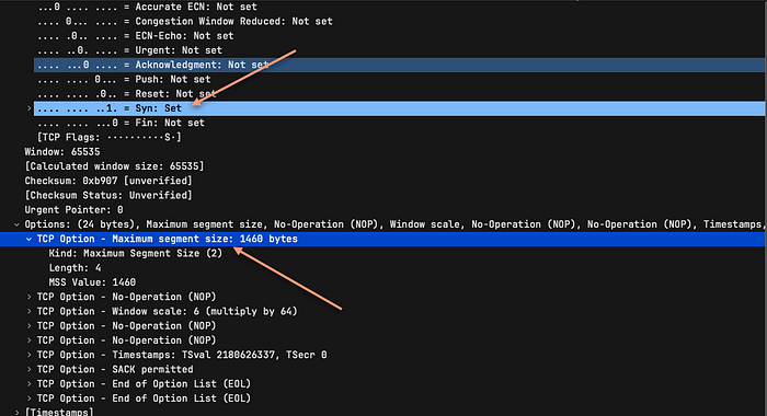
You can observe the MSS (Maximum Segment Size) negotiations in Wireshark during the TCP handshake process. Here’s how to find and analyze the MSS negotiation:
SYN Packet:
- Expand the TCP section and look for “Options.”
- You will find an entry like “Maximum segment size: 1460 bytes.”
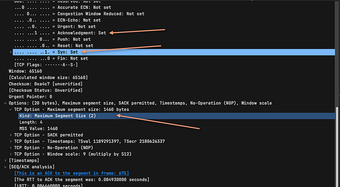
SYN-ACK Packet:
- Again, expand the TCP section and look for “Options.”
- You might find an entry like “Maximum segment size: 1460 bytes” or a different value depending on the server’s capabilities and configuration.
Example Scenario
Client Side:
- The client has an MTU of 1500 bytes.
- The client sends a SYN packet with an MSS option of 1460 bytes (1500 bytes MTU minus 20 bytes IP header and 20 bytes TCP header).
Server Side:
- The server might have a different MTU, say 1400 bytes.
- The server responds with a SYN-ACK packet and an MSS option of 1360 bytes (1400 bytes MTU minus 20 bytes IP header and 20 bytes TCP header).
Result:
- Both client and server will use the smaller MSS value (1360 bytes) for their TCP segments to ensure that the data packets do not exceed the MTU of any segment of the network path.
In conclusion, understanding the concepts of Maximum Transmission Unit (MTU) and Maximum Segment Size (MSS) is critical for optimizing network performance. While these parameters are related, they serve different roles in the networking process. The Ethernet frame has a maximum size of 1518 bytes, with the payload (MTU) being 1500 bytes. This payload is further divided at the IP and TCP layers, leaving an MSS of 1460 bytes. By understanding how data is encapsulated and transmitted across networks, one can effectively adjust these parameters to enhance network efficiency and reliability.
